Technical Note
OFDR-based Distributed Strain & Temperature Sensing
June 2026
1. Introduction to APEX Technologies OFDR System
The OFDR system developed by APEX Technologies is a high-performance instrument designed for high-resolution characterization of optical fibers and photonic components. The device is built around a tunable laser source that performs a controlled frequency sweep, combined with a coherent detection scheme to capture the backscattered signal with high sensitivity.
Designed to support R&D engineers and researchers in the development and optimization of photonic devices, the system offers versatile measurement capabilities, including high-performance evaluation of return losses and insertion losses, in reflection and transmission as well as spectral and polarization analysis. Figure 1 below shows an example measurement done with the OFDR.
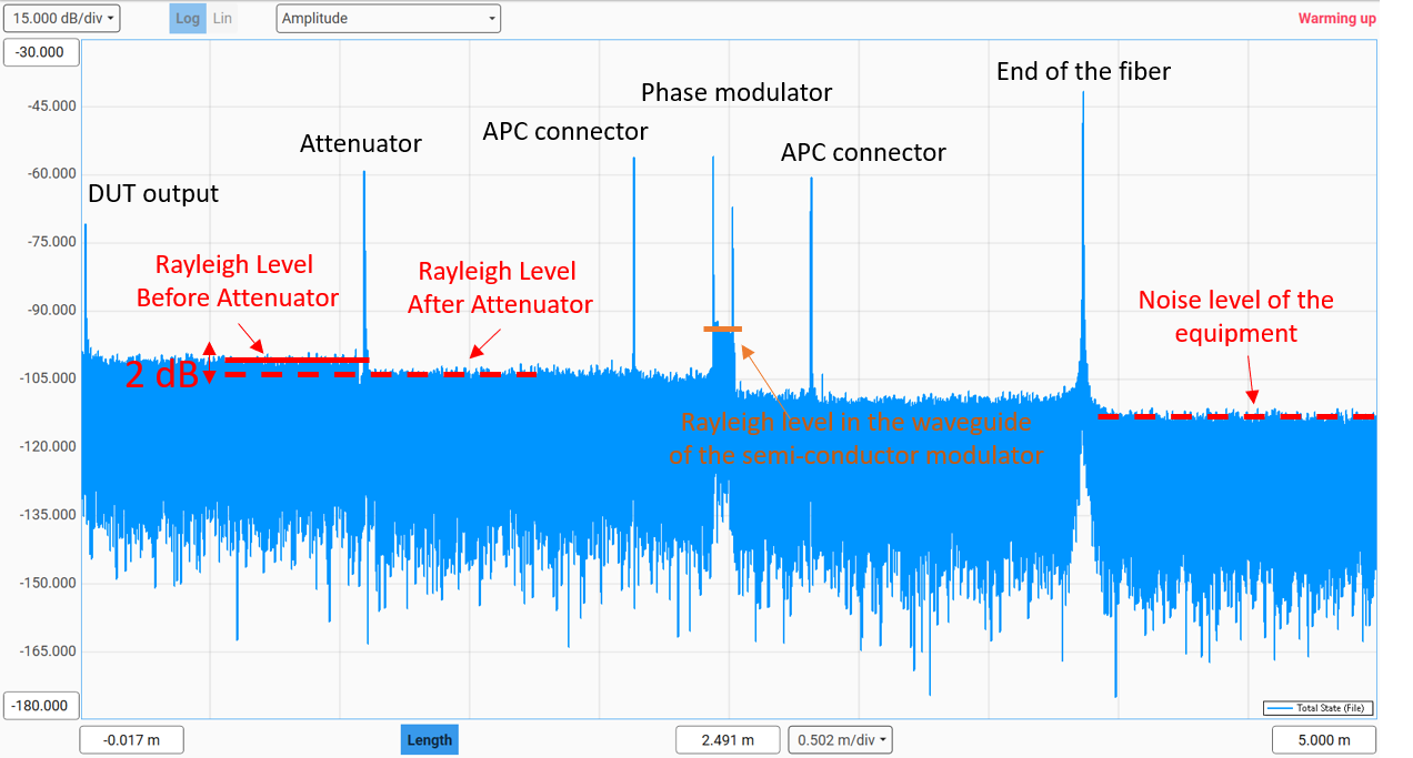
Figure 1: Attenuator and phase modulator measurement done on APEX Technologies OFDR
A useful distinction can be made between conventional OTDR, coherent OTDR techniques (φ-OTDR / DAS), OLCR, and OFDR. Conventional OTDR relies on the analysis of backscattered optical power in the time domain and is primarily used for fault localization and loss characterization over long fiber distances. Coherent OTDR techniques enhance sensitivity by measuring both the amplitude and phase of the backscattered signal, enabling the detection of dynamic events such as vibrations and acoustic disturbances over several kilometers. OLCR (Optical Low-Coherence Reflectometry) is based on low-coherence interferometry and provides extremely high spatial resolution, typically in the tens-of-micrometers range. However, its measurement range is generally limited compared to other reflectometry techniques. OFDR, on the other hand, operates in the frequency domain using a swept laser and coherent detection, allowing the backscatter signature of the fiber to be resolved with very high spatial resolution, from the millimeter down to the sub-millimeter scale, while maintaining significantly longer measurement ranges.
| Features | phi-OTDR | OLCR | OFDR |
| Measurement Domain | Time Domain | Time/Delay Domain | Frequency/Spectral Domain |
| Mechanism | Pulses ToF | Interferometry (Michelson-type) | Interferometry(Swept CW Laser) |
| Max Range | Up to 100+ km | Tens of meters | Few hundred meters |
| Spatial Resolution | Meters | Micrometers | Micrometers |
| Distributed Sensing | ✅ | ⚠️ | ✅ |
| Main Strength | Dynamic sensing over long range | Ultra-high resolution | Ultra-high resolution + Distributed sensing |
Table 1. Comparison of reflectometry techniques
In addition to its characterization capabilities, OFDR is a powerful platform for distributed measurements, enabling the continuous monitoring of physical parameters such as strain and temperature along the entire length of an optical fiber. When the fiber is subjected to external influences such as temperature changes or mechanical strain, the local optical properties of the fiber are modified, leading to measurable shifts in the backscattered signal. By comparing this signal to a reference state, it is possible to accurately determine both the magnitude and the position of these variations. Thanks to its high spatial resolution, localized changes can be accurately detected and correlated with their position within the monitored structure[1].
These capabilities make OFDR particularly valuable in fields such as civil engineering, aerospace, energy, and even healthcare, where the ability to obtain high spatial resolution measurements along an optical fiber provides information that would be difficult (or impossible) or impractical to obtain using conventional point sensors.
In civil engineering, structural health monitoring uses distributed strain measurements to assess the condition of large infrastructures such as bridges, buildings, and other reinforced concrete structures. Because the strain profile is measured continuously along the fiber, localized stress concentrations, crack initiation, or deformation can be identified before visible damage occurs. This capability is particularly useful for long-term monitoring of critical infrastructure and for validating structural models during load testing. Several studies have demonstrated the use of OFDR-based distributed sensing where millimeter-scale spatial resolution enables the detection of highly localized strain variations.[2] [3]
In the aerospace sector, OFDR is increasingly used to monitor composite materials and lightweight structures. Modern aircraft rely heavily on carbon-fiber-reinforced composites, whose failure mechanisms can be difficult to detect using conventional instrumentation. By embedding or surface-bonding optical fibers, engineers can obtain detailed strain maps over large areas and identify regions experiencing abnormal loading, delamination, or impact damage. The micrometer-scale spatial resolution offered by OFDR is particularly attractive for aeronautical structures, where small defects can have a significant impact on structural integrity. Applications have been reported on composite panels, wing-box structures, and full-scale aerospace components.[4]
Satellite thermal-vacuum (TVAC) testing also benefits from OFDR distributed sensing measurements. Satellites (or sub-modules) are cycled between temperature extremes in a vacuum chamber to simulate the orbital environment, and optical fibers are used to map the resulting temperature distribution across panels and structures, replacing the hundreds of thermocouples normally harnessed on for the test. As the structure cycles over extreme temperatures, mismatches in coefficient of thermal expansion between materials (composite panels, honeycomb, fittings, harnesses) produce thermomechanical strain threatening structural integrity over the mission; the OFDR and the optical fibers (multicore fibers are particularly useful here) will measure it for deep insights on the mechanical behavior, replacing traditional strain gauges.
In the energy sector, distributed temperature and strain measurements can provide valuable information for the monitoring of batteries[5], power-generation equipment, industrial processes, and renewable-energy assets. Wind turbine blades, for example, are subject to complex loading conditions that evolve over time. Distributed fiber-optic measurements make it possible to track strain distributions along the structure. Similarly, temperature profiling can be used to detect hot spots, evaluate thermal gradients, and improve the safety and efficiency of energy systems. Distributed fiber-optic sensing has been successfully applied to both wind turbine structures and large-scale industrial monitoring applications. [6] [7]
The present application note focuses on distributed strain measurements. The following sections demonstrate the capability of the OFDR system to accurately quantify applied strain using experimental data obtained under controlled laboratory conditions.
2. Sensing Measurements
2.1 Experimental Setup
In order to test the sensing capabilities of the APEX Technologies OFDR, a tensile experimental setup (as shown in Figure 2) was implemented to apply controlled strain to an optical fiber. The setup was built on an optical rail to ensure stability and precise alignment of all components. Two micrometer translation stages were mounted along the rail axis, allowing accurate and repeatable displacement.
The optical fiber under test was prepared by fixing its ends into metal plates with V-groove clamps, ensuring proper axial alignment and mechanical stability. These plates were then attached to the translation stages. Strain was applied by incrementally moving one of the micrometer stages while keeping the second fixed. The fiber elongation was performed step by step, with each increment corresponding to approximately 2000 µstrain, enabling precise evaluation of the sensing response.
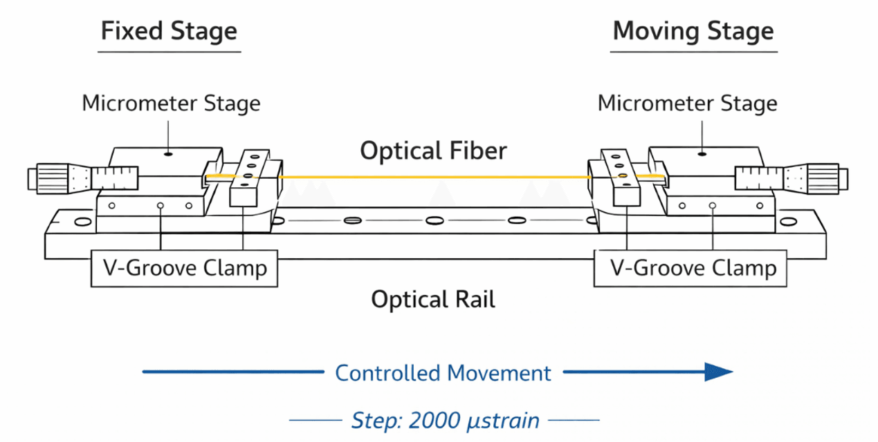
Figure 2. Tensile experimental setup
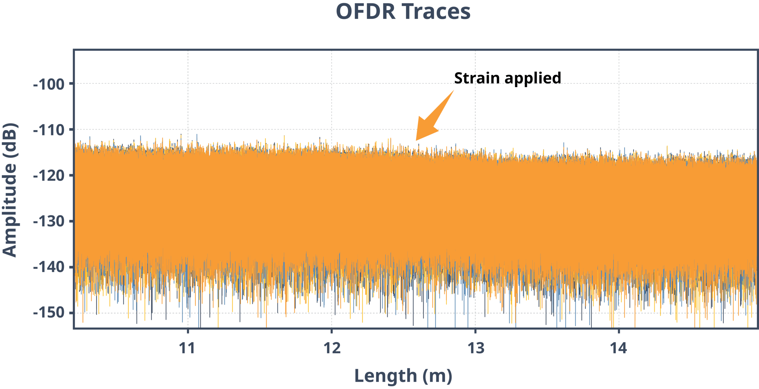
Figure 3. Raw OFDR measurements
2.2 Performance Evaluation
The experiments enabled a frequency shift of approximately 800 GHz, corresponding to an optical sweep range of about 8 nm. This result highlights the high sensitivity of the measurement, while also indicating that further improvements in range and stability remain achievable. Extending the applied strain beyond 10,000 µε is of particular interest; although material non-linearity may arise in this regime, exploring these higher strain levels would provide valuable insight into the behavior of the fiber as well as the performance limits of the APEX Technologies OFDR system under more demanding conditions.
Shown on Figure 4, the graph illustrates the change of the measured spectral shift and the applied strain along the optical fiber. As the strain increases, a proportional shift in frequency is observed, confirming the expected behavior of the sensing mechanism. The slope of the curve corresponds to the strain sensitivity coefficient, which is consistent with theoretical predictions and reference measurements. This linearity demonstrates the accuracy and reliability of the OFDR-based sensing approach for quantitative strain evaluation.
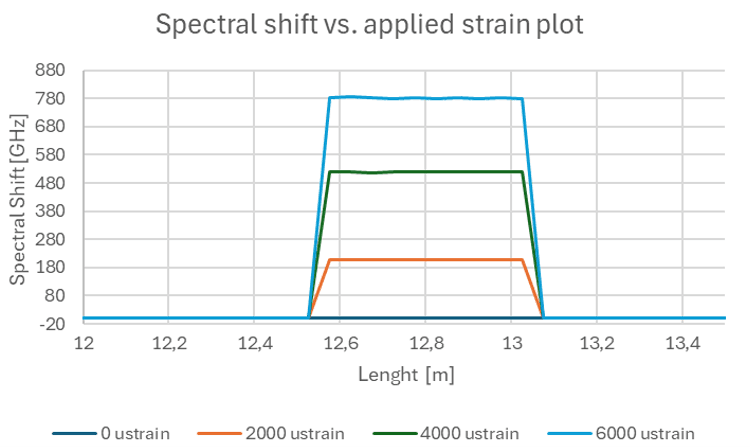
Figure 4. Spectral shift over optical fiber length
The sensitivity curve illustrated on Figure 5 shows the relationship between the measured response and the applied strain, highlighting the consistency of the sensing coefficient over the tested range. The curve shows a stable and nearly constant sensitivity, indicating that the system maintains a linear and predictable behavior. This confirms that the OFDR-based measurement provides reliable strain quantification, with minimal deviation across the operating range.
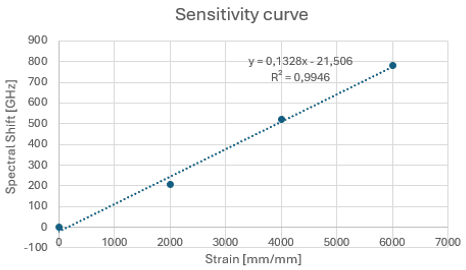
Figure 5. Correlation between applied strain and OFDR spectral shift.
At this stage, the measurement setup constitutes a limiting factor in terms of repeatability and accuracy. Ongoing developments include the design of a capstan adapter for the micrometer stage, aimed at improving strain control and reducing mechanical variability. This enhancement is expected to enable more consistent and repeatable measurements, aligned with standard metrology practices, and to support further optimization of the sensing performance.
In the next stages, further investigations will be carried out once the demonstration unit becomes available again, with the objective of exploring additional aspects of system performance. These include the evaluation of temperature response, the effective measurement range over extended fiber lengths, long-term stability with respect to reference measurement, and the characterization of the dead zone near the fiber end. Such analyses will provide a more comprehensive assessment of the capabilities and limitations of the APEX Technologies OFDR system.
In parallel, additional experiments are planned to assess sensing performance on optical fibers with different metallic coatings. With recent in-house capabilities enabling metal coating deposition, particular focus will be placed on copper and nickel coatings. These investigations will include both strain measurements and temperature sensing at elevated levels, with target ranges reaching up to 800 °C. This work will help evaluate the adaptability of the sensing approach to more demanding environments and broaden the scope of potential applications.
2.3 Future work
The next phase of work will focus on extending the validation of the sensing capabilities under more demanding conditions. Planned activities include advanced strain testing up to at least 10,000 µε, as well as verification of the temperature coefficient up to +200 °C. In addition, specific targets have been defined for high-temperature operation, with expected ranges of approximately 300 °C for polyimide-coated fibers and up to 600 °C for copper-coated fibers.
Long-distance measurements will also be investigated over fiber lengths exceeding 100 m, with a target of around 250 m, in order to ensure that the APEX Technologies OFDR system maintains data integrity up to the end of the sensing fiber—an aspect that has shown limitations in other instruments.
Further analysis will address the impact of Fresnel reflections at the fiber end. Different termination configurations will be compared, including fiber loops, coreless fiber sections, APC connectors, and a dedicated termination fiber. The objective is to evaluate how each termination type influences the measurement quality, particularly in terms of signal degradation and potential loss of sensing information.
Acknowledgements
The authors are grateful to Jakub Koryciński and Daniel Lis from Interlab for providing their experimental setup and data.
References
[1] Distributed Optical Fiber Sensors Based on Optical Frequency Domain Reflectometry: A review
[2] A Review of Recent Distributed Optical Fiber Sensors Applications for Civil Engineering Structural Health Monitoring
[3] Optical frequency domain reflectometry-based high-performance distributed sensing empowered by a data and physics-driven neural network
[4] Advanced Fiber Optic Sensing Technology in Aerospace: Packaging, Bonding, and Calibration Review
[5] Operando monitoring of strain field distribution in lithium battery
anode via ultra-high spatial resolution optical frequency domain reflectometer
[6] Wind-turbine wake effects on the rate of accumulation of fatigue damage in
overhead conductors
[7] Preliminary Test for 3D Surface Strain Measurement in the Tower and Foundation of Offshore Wind Turbines Using DOFS


Copyright © 2026 Apex Technologies